EN


Electric Bike Controller Wiring: Connector Checks Before Replacing a Motor Cable
When an e-bike loses drive, cuts out under load, or shows an intermittent motor fault, it is tempting to order a replacement cable immediately. Yet electric bike controller wiring is a compatibility system, not a collection of interchangeable colored leads. A cable can look similar and still have a different connector key, pin count, wire order, or controller-side assignment. The careful approach is to inspect and document what is on the bike before disconnecting anything.
This guide focuses on connector checks before a motor-cable replacement. It is written for owners, repair shops, and buyers sourcing parts for a specific model. If insulation is melted, a connector is deformed, or the wiring diagram is unavailable, pause the work and use the manufacturer’s verified information or a qualified e-bike technician.
Start With a Safe, Repeatable Inspection
Before examining electric bike controller wiring, power the bike down, remove or isolate the battery according to the bike’s instructions, and wait for the system to de-energize. Keep the work area dry and avoid probing live connectors with improvised tools. Take clear photos before unplugging a connection: one wide photo showing cable routing, then close-ups of each mating face, latch, seal, and label.
A common sourcing mistake is to rely on wire color alone. Color may be useful as a record of the original harness, but it is not proof that two connectors share the same pinout. Connector housing shape, index tabs, latch position, pin layout, cable exit direction, and any printed code are stronger starting points for an electric bike controller wiring comparison.
Identify the Motor Connections Without Making Assumptions
Many brushless hub-motor systems have separate high-current motor phase conductors and a smaller signal connector for Hall sensors. The former are often heavier-gauge conductors; the latter may carry several smaller wires. That observation helps organize an inspection, but it is not a universal wiring diagram. Some models combine circuits in a single connector, add speed-sensor or temperature leads, or use a manufacturer-specific harness.
For each connection associated with electric bike controller wiring, record:
- connector type and housing color;
- number of cavities and number of populated pins;
- keying ribs, arrows, latch style, and waterproof seals;
- wire count, approximate wire size, and cable length;
- printed markings on the controller, motor cable, and old harness;
- where the cable enters the motor axle and where it reaches the controller.
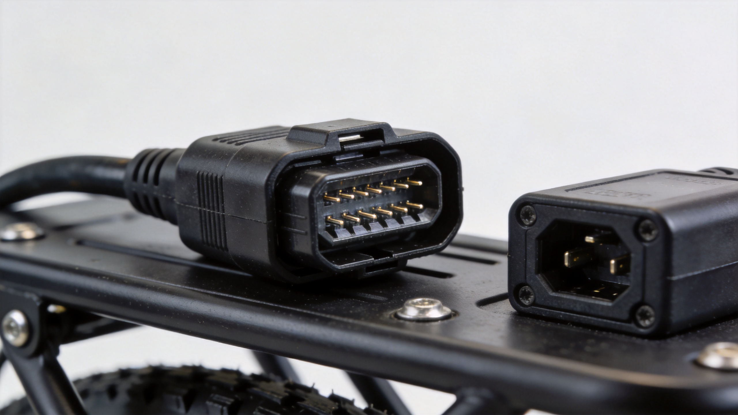
Do not force a plug that is almost aligned. A connector that does not mate smoothly may have the wrong keying or a displaced terminal. Forced mating can damage the housing or bend contacts, creating a new ebike controller troubleshooting issue after the original cable has been replaced.
Check the Connector Condition Before Blaming the Cable
A useful electric bike controller wiring inspection has two parts: external condition and mechanical engagement. Look for chafed insulation, flattened cable sections, cracked strain relief, exposed conductor, moisture residue, greenish corrosion, darkened plastic, or a loose retaining latch. At the mating face, inspect whether terminals are recessed, bent, pushed back, or unevenly spaced. Compare both sides; damage at the controller connector can mimic a failed motor lead.
Gently check whether the joined connector has excessive play. A harness can appear connected while a terminal is not fully seated. This matters especially after a fall, transport damage, repeated folding, or routing near a moving suspension or wheel area. In electric bike controller wiring, the physical path matters as much as the connector itself: a cable pulled tightly around a hinge, rough frame edge, or axle exit is likely to see repeated stress.
Use a Connector Checklist, Not a Color-Matching Shortcut
For repair purchasing, make a simple side-by-side checklist for the old cable and the proposed replacement. Confirm the model and controller part number first. Then compare connector family, pin count, keying, cable length, exit orientation, and function. Only after those checks should you compare conductor colors against verified documentation for that exact controller and motor combination.
| What to verify | Why it matters | What to record |
|---|---|---|
| Bike and controller identification | Similar-looking controller housings may use different harness assignments. | Bike model, model year if known, controller label, part number. |
| Motor-side connector | Keying and cavity layout determine whether the plug can mate correctly. | Front and side photos, pin count, latch position. |
| Cable route and length | A correct connector is still unsuitable if the cable cannot follow the original route without tension. | Approximate length and routing photos. |
| Visible damage | Damage may identify a localized repair need rather than a full-harness issue. | Close-up images of wear, heat marks, or corrosion. |
This checklist makes electric bike controller wiring requests clearer for a supplier or service team. It also reduces the chance that a replacement is selected from a generic image rather than from the exact connector arrangement on the bike.
What to Photograph and Send When Requesting a Replacement
For a model-specific request, include the bike model, the controller label, a photo of the old motor cable laid flat, and close-ups of both disconnected connector faces. Add a photo of the controller socket and motor-side socket, not just the outside of the plug. If a label, production code, or harness marking is present, transcribe it exactly.
For example, buyers working on an EP-2 Pro repair can compare their documented connector arrangement with the product information for a motor connection cable for Engwe EP-2 Pro. If the inspection suggests that the controller itself also needs review, the separate Engwe EP-2 Pro controller replacement listing can help identify the relevant component. Treat product pages as part-identification aids; they do not replace the bike’s verified wiring documentation.
Know When to Stop the DIY Check
Stop and seek model-specific technical support if you find melted insulation, a burnt smell, liquid inside a connector, exposed copper, a damaged battery lead, or uncertainty about terminal order. Do not join mismatched plugs by cutting and twisting wires simply to see whether the motor runs. That approach can make later diagnosis harder and may damage components.
The most reliable electric bike controller wiring process is conservative: document first, compare verified connection details second, and install only when the replacement matches the identified system. For a workshop or parts buyer, those extra photos and notes turn a vague cable request into a checkable compatibility record.
Pre-Replacement Summary
Before replacing a motor cable, isolate the battery, photograph every connection, inspect housings and terminals, record connector details, and confirm the controller and bike identifiers. In electric bike controller wiring, colors are clues—not a final decision. A replacement cable should match the documented connector format and routing requirements, while any damaged or uncertain electrical connection deserves verified technical guidance before reconnection.
Quick FAQ
Can wire colors confirm electric bike controller wiring compatibility?
No. For electric bike controller wiring, colors help document the original harness but should be checked against the connector arrangement, pin count, keying, controller label, and verified model information.
Why inspect a connector before replacing a motor cable?
A loose, corroded, heat-marked, or damaged connector can cause the same symptoms that lead to ebike controller troubleshooting. Inspecting it first helps determine whether the cable, connector, controller, or another part needs attention.