EN


How to Choose an E-Bike Controller Kit with LCD, Throttle and PAS
Replacing a controller is rarely a matter of matching one plug. An electric bike pedal assist sensor works inside a system that also includes the battery, motor, controller, display, throttle, brake cutoffs, and wiring harness. For a repair shop, distributor, or conversion buyer, the safest purchase decision starts with the system specification—not the appearance of the LCD or the number of loose connectors in the box.
This guide explains how to compare a kit that includes an LCD, throttle, and PAS. It focuses on the checks that prevent a replacement electric bike pedal assist sensor from becoming a connector, voltage, or programming mismatch.
First, Separate the Jobs of the LCD, Throttle, PAS, and Controller
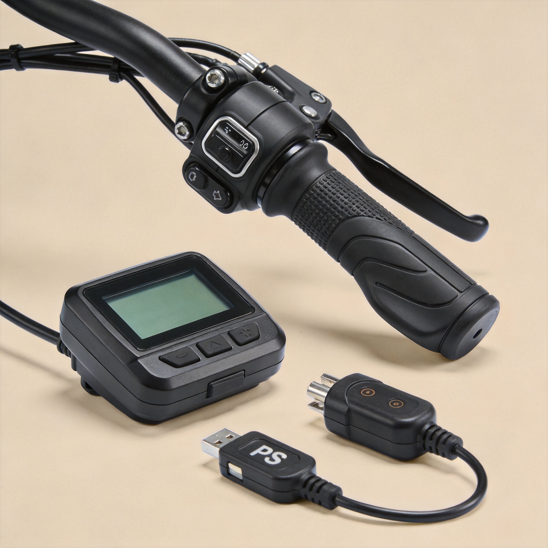
The controller is the decision-making unit. It receives signals, manages motor output, and enforces the settings it has been designed or programmed to use. The LCD is the rider interface: depending on the matched system, it may show speed, battery information, assist level, fault codes, and settings. A throttle asks for power directly, while an electric bike pedal assist sensor tells the controller that the crank is turning—or, in a torque-based design, how hard the rider is pedaling.
An ebike pedal assist sensor is therefore not a motor controller, and an LCD is not automatically compatible simply because both have waterproof connectors. A kit is useful when its controller, display, throttle, and PAS are specified to work together. Treat every component as part of one communication and wiring system.
Start with the Battery, Motor, and Controller Rating
Before comparing an electric bike pedal assist sensor, record the battery’s nominal voltage, the motor type, and the controller’s intended power range. The battery and controller must be designed for the same voltage family. A controller intended for 24 V, 36 V, or 48 V use may cover more than one voltage only when its product specification explicitly says so. Do not infer multi-voltage capability from a similar enclosure or connector.
Next, identify whether the motor and controller are brushless and whether the motor uses Hall sensors. A dual-mode controller can be helpful in some repair scenarios, but it does not remove the need to verify phase-wire layout, Hall plug format, current capability, and motor condition. The electric bike pedal assist sensor still needs a compatible low-voltage supply and signal input from that controller.
For a practical example, the New Image brushless dual-mode e-bike controller kit with LCD, throttle and PAS is listed for 24 V/36 V/48 V and 250 W–350 W applications. Use the listing as a starting point, then confirm the exact battery, motor, and connector arrangement for the bicycle being repaired.
Check PAS Fitment Before You Choose an Electric Bike Pedal Assist Sensor
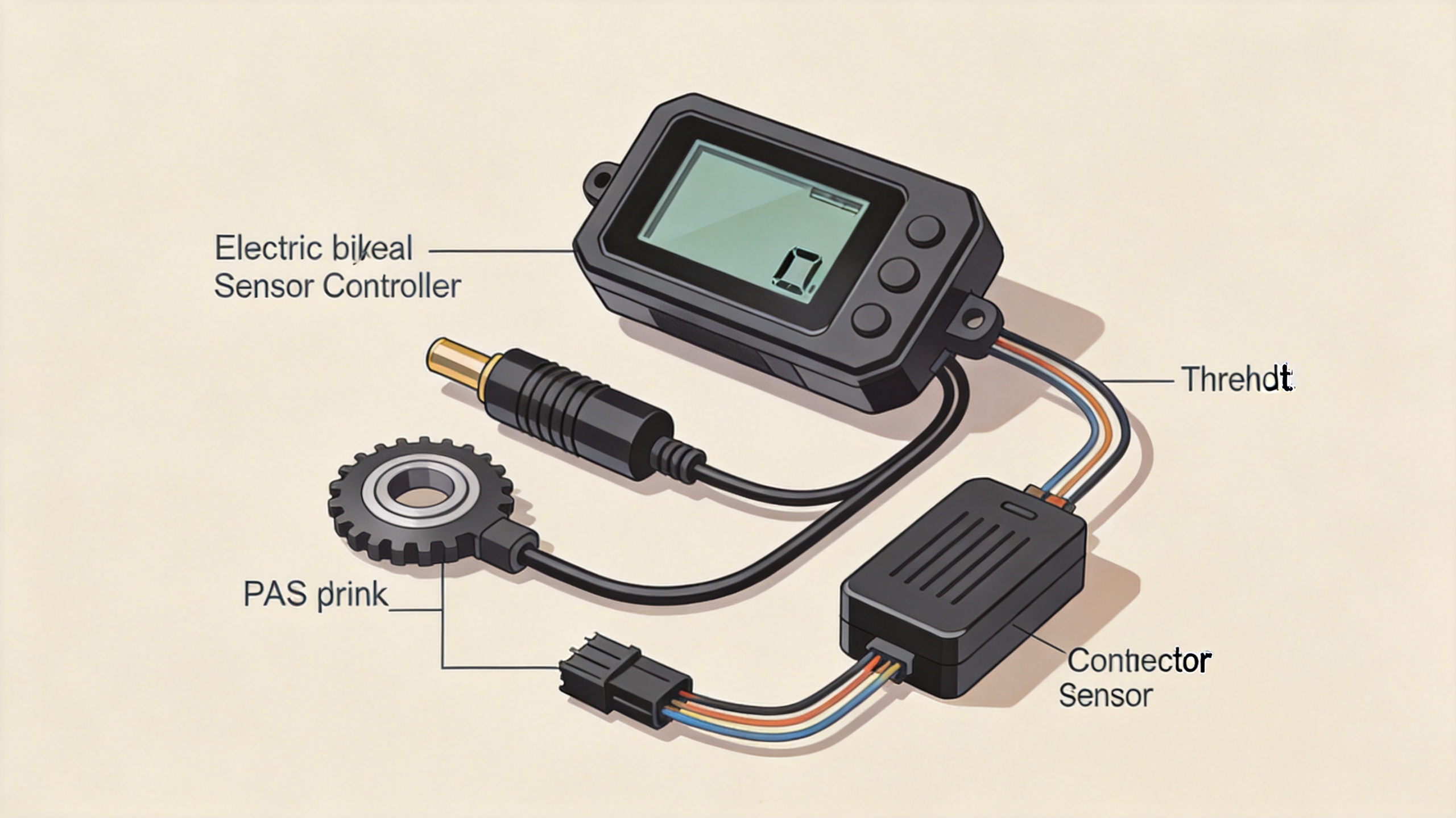
For an electric bike pedal assist sensor, physical fitment matters as much as electrical fitment. Check whether the sensor is intended for the bicycle’s bottom-bracket area, whether there is clearance around the crank, and which side and mounting style the magnet disc requires. A cadence-style sensor commonly detects crank rotation; the controller uses those pulses to decide when pedal assistance should begin.
Then compare connector shape, pin count, keyway, wire colors, and signal arrangement. A three-pin plug is common in some systems, but it is not a universal wiring standard. Do not join wires by color alone. Ask for a wiring diagram, label each existing connector before disassembly, and use the kit documentation to verify the electric bike pedal assist sensor input.
If the old bicycle has a torque sensor, a simple cadence electric bike pedal assist sensor may not provide the same riding behavior or use the same controller input. That is a system change, not just a sensor replacement.
Match the LCD to the Controller Protocol
Buyers often focus on the LCD because it is visible, but the display can be the least interchangeable part of a kit. The LCD may exchange power, settings, and error information through a manufacturer-specific communication protocol. An LCD connector that physically mates with a controller can still fail to show correct data or allow configuration if the protocol differs.
When selecting a kit, verify that the LCD is supplied as a matched component rather than as a visually similar standalone display. Confirm the controller’s display connector, supported voltage, connector length, mounting diameter, and configuration options. Once connected, check whether the LCD reads battery status, changes assist levels, and reports errors consistently. These checks help prove that the electric bike pedal assist sensor and display are communicating through the correct controller rather than merely receiving power.
Decide Whether a Twist Throttle Fits the Intended Market and Riding Use
An electric bike with twist throttle can offer convenient starts and low-speed maneuvering, but the throttle must be assessed separately from PAS. Verify that the controller supports the throttle type and that the throttle plug is part of the supplied harness. Also confirm brake cutoff inputs: if the kit supports them, a pulled brake lever should command the controller to stop motor drive.
Market rules matter. Some European pedelec use cases are commonly associated with 250 W continuous rated power and assistance that cuts off at 25 km/h, while regulations elsewhere may use different classifications and throttle rules. A compliant purchase decision requires checking the applicable local requirements before installation. Neither an electric bike pedal assist sensor nor an LCD setting alone guarantees legal road use.
Use a Compatibility Checklist Before Installation
- Confirm the battery’s nominal voltage and connector condition.
- Identify motor type, Hall-sensor arrangement, and controller power range.
- Verify that the LCD is the controller’s intended display model.
- Check the electric bike pedal assist sensor mounting position, magnet-disc direction, clearance, plug, and pinout.
- Confirm throttle, brake cutoff, light, and speed-sensor connectors only where the controller documentation identifies them.
- Review local requirements for power, assisted speed, and throttle operation.
During a bench test, keep the drive wheel clear of the ground. Power the system, confirm the LCD functions, rotate the cranks to test the electric bike pedal assist sensor, and test brake cutoffs before a road test. Investigate fault codes or unexpected motor behavior before final cable routing.
Choose a Complete Kit When the Original System Is Uncertain
When replacing only one failed part, exact compatibility evidence is essential. When several original components are damaged, undocumented, or missing, a matched LCD-throttle-PAS-controller kit can reduce uncertainty because the core interfaces are supplied together. It still must match the battery and motor, but it removes several cross-brand interface variables.
The strongest purchasing request includes photographs of existing labels and connectors, battery voltage, motor information, wheel or bicycle type, and the desired riding behavior. That gives a supplier the information needed to assess the controller, LCD, throttle, and electric bike pedal assist sensor as one working package. For B2B buyers, documenting these details also makes incoming inspection and customer support more repeatable.
Conclusion
The right kit is not defined by an LCD screen or a throttle alone. Start with battery and motor compatibility, then verify controller rating, display protocol, throttle support, and the physical and electrical fit of the electric bike pedal assist sensor. A structured check before ordering reduces rework, helps protect components during installation, and makes the finished e-bike system easier to diagnose and maintain.