EN
EN


BLDC Motor Drive Basics: What an E-Bike Controller Does
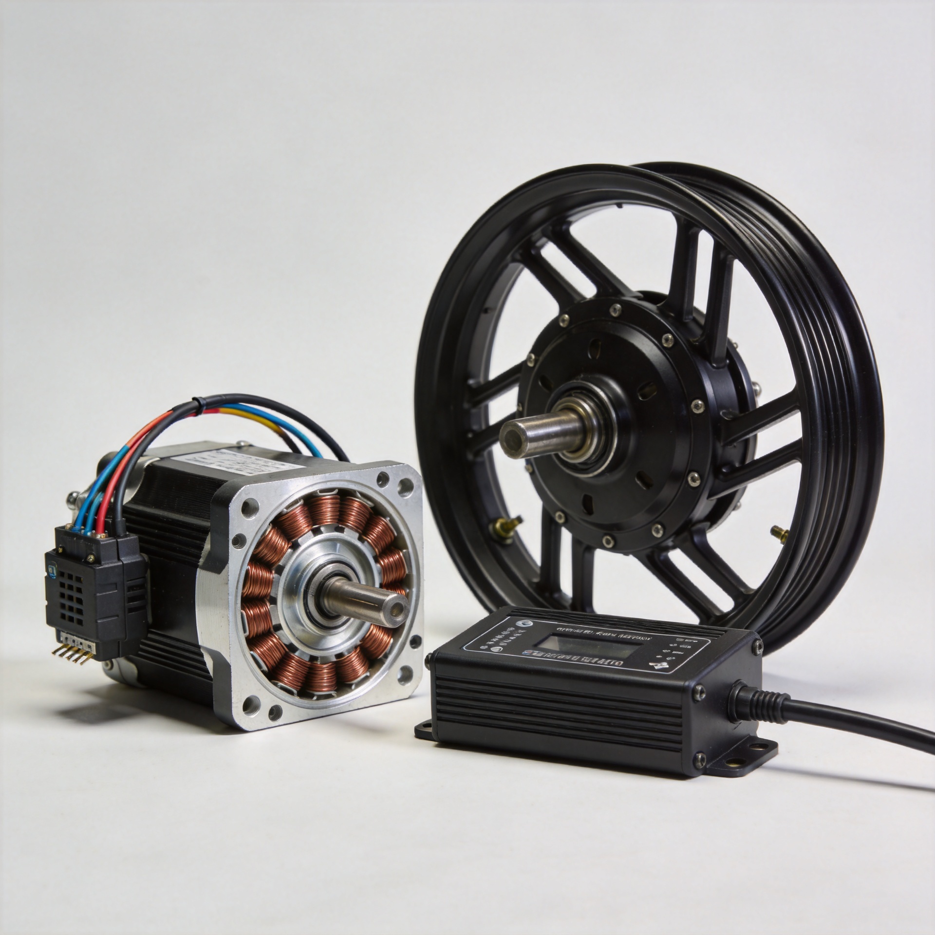
A brushless dc motor drive is the electronic system that makes a brushless hub motor move in a controlled way. On an e-bike, the controller is the practical “traffic manager” between the battery, throttle or pedal-assist commands, and the motor. It decides when and how much current reaches the motor phases, which affects starting feel, acceleration, climbing behavior, and protection response.
This matters whenever you diagnose a no-start condition, specify replacement parts, or compare controllers for a fleet. A controller that looks similar may still be wrong for the battery voltage, motor wiring, or display protocol. The safest starting point is to understand the job of the drive before comparing labels and connectors.
What makes a BLDC system different?
A conventional brushed DC motor uses brushes and a mechanical commutator to switch current inside the motor. A brushless dc bldc motor does not use that mechanical switching arrangement. Instead, the controller performs electronic commutation: it energizes the motor’s phase windings in sequence so the permanent-magnet rotor keeps turning.
In plain language, the motor supplies the rotating force, while the brushless dc motor drive supplies the timing. The controller continuously interprets inputs and sends a changing pattern of current through the phase wires. That is why the controller is not merely an on/off box. It is responsible for coordinating a three-phase system as riding conditions change.
For an awareness-stage explanation, it helps to separate the roles clearly:
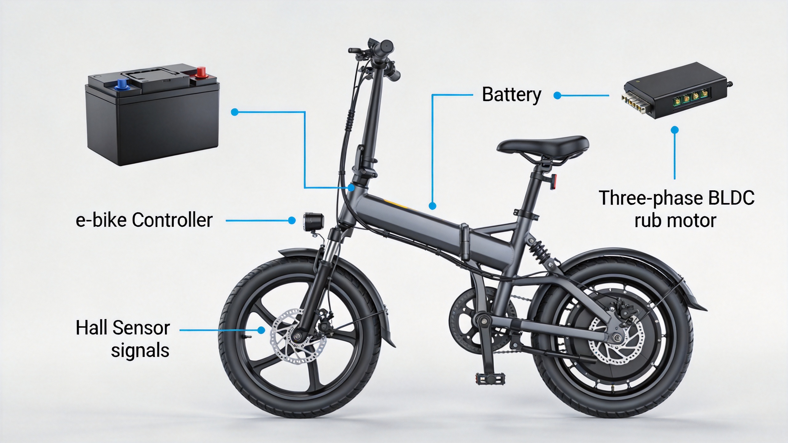
- Battery: provides DC power.
- Controller: converts rider commands into controlled phase-current switching and applies limits.
- BLDC motor: converts that controlled electrical energy into wheel torque.
- Throttle, pedal assist, brakes, and display: provide commands or status signals, depending on the system design.
What an e-bike controller actually controls
The first job of a brushless dc drive is commutation. With a sensored motor, Hall sensors report rotor position so the controller can choose the next phase sequence. With a sensorless design, the controller estimates rotor position from electrical feedback. Either approach is intended to keep the magnetic field moving in the correct relationship to the rotor.
The second job is current management. When the rider requests power, the controller does not simply pass the battery directly to the motor. It regulates current according to its programming and hardware limits. This is a key reason two controllers used with the same nominal battery voltage can produce different acceleration or hill-climbing behavior.
The third job is protection. Depending on its design, an e-bike controller may reduce or stop output for low battery voltage, excessive current, overheating, brake input, or an abnormal motor signal. Confirm exact thresholds from the controller documentation.
Why voltage compatibility comes first
Before replacing a controller, confirm the battery system voltage and the controller’s supported input range. The nominal label alone is not enough. For example, a typical 48 V lithium-ion pack is commonly built as 13 cells in series and reaches about 54.6 V when fully charged. The controller must be designed to tolerate that full-charge voltage, not only the nominal 48 V description.
If you are mainly matching replacement parts for a familiar vehicle, voltage is still the first checkpoint. A connector that physically fits does not prove electrical compatibility. Verify the battery label, the controller label, and—when available—the manufacturer wiring diagram. For service teams, recording the measured pack voltage before installation can prevent a costly mismatch.
Current rating: useful, but not a shortcut
Controller current limits influence how strongly the system can drive the motor. However, more current is not automatically a better upgrade. The battery’s continuous-discharge capability, the motor’s thermal limits, cable sizing, and the intended riding load all matter. A high-current controller paired with an unsuitable battery or motor can increase heat and stress even if the nominal voltage matches.
Many buyers initially compare only a controller’s headline amperage. In practice, compatibility is more important than a larger number. Treat the rating as one part of a system check: battery capability, controller limit, motor type, cooling conditions, and riding duty cycle should be reviewed together.
Phase wires, Hall sensors, and communication connectors
A common brushless dc motor drive arrangement uses three heavier phase wires plus a smaller Hall-sensor harness. A Hall harness often includes a supply wire, ground, and three signal wires, but colors and connector pinouts are not universal. Do not rely on color alone when mixing components from different models or suppliers.
This is where many replacement attempts go wrong. A controller may share the same plug shape while using a different pin order, voltage logic, display protocol, or self-learning procedure. Confirm the motor phase arrangement, Hall-sensor pinout, throttle connector, brake input, display or communication wiring, and any speed-limit or ignition leads before applying power. If the documentation is incomplete, a qualified technician should validate the connections.
A practical controller replacement checklist
- Read the battery’s nominal voltage and full-charge voltage specification.
- Confirm the replacement controller supports that battery range.
- Check the motor type, rated system voltage, phase-wire connector, and Hall-sensor connector.
- Compare controller current limits with battery capability and the motor’s intended application.
- Verify throttle, brake cutoff, pedal-assist, display, and lighting connectors or communication protocols.
- Inspect wire condition, connector locking, insulation, and signs of heat damage before installation.
- Test with the driven wheel safely off the ground first, following the vehicle manufacturer’s service guidance.
Where a universal controller can fit—and where it may not
Universal replacement controllers can be useful when voltage, motor wiring, control inputs, and mounting requirements are confirmed. They are not automatically plug-and-play across all e-bikes. Brand-specific displays, proprietary communication systems, and integrated battery-management behavior may require a matched controller.
For a 48 V application, the High Current 48V 21A Speed-Unlimited Controller for Electric Bicycles is an example of a controller option to assess against the vehicle’s documented voltage and wiring requirements. Its listing title does not replace a compatibility check; confirm all electrical and connector details before specifying it for a particular model.
BLDC controller terms to recognize on a specification sheet
When comparing a brushless dc motor drive, the vocabulary on the label can be more useful than a marketing claim. This quick reference helps purchasing and service teams ask consistent questions about a brushless dc drive before a replacement order is placed.
| Term | What it means in an e-bike system | What to verify |
|---|---|---|
| Brushless dc motor drive input voltage | The battery range the brushless dc motor drive is designed to accept. | Nominal voltage and maximum fully charged battery voltage. |
| Current limit | The limit used by the brushless dc drive to manage battery and motor current. | Battery continuous-discharge capability and thermal margin. |
| Phase output | The three motor connections sequenced by the brushless dc motor drive. | Connector type, wire condition, and correct phase arrangement. |
| Hall input | Rotor-position signals used by a sensored brushless dc bldc motor system. | Pinout, supply logic, and whether the motor is sensored. |
| Low-voltage protection | A cutoff or reduction function inside the brushless dc drive. | Compatibility with the battery chemistry and pack voltage. |
| Control interface | Throttle, PAS, brake, display, or communication inputs to the brushless dc motor drive. | Connector mapping and protocol requirements. |
Questions to ask before ordering a brushless DC drive
- Does this brushless dc motor drive support my battery’s nominal and full-charge voltage?
- Is the brushless dc drive current limit appropriate for the battery and motor rather than simply higher?
- Is the motor a sensored brushless dc bldc motor, sensorless motor, or a design that supports both?
- Are the phase wires, Hall connector, throttle input, brake cutoff, and display plugs documented for this brushless dc motor drive?
Key takeaway
The controller is the operating center of a brushless dc motor drive: it performs electronic commutation, manages current, and coordinates protective responses. For replacement decisions, begin with voltage and full-charge tolerance, then validate current capability, phase and Hall wiring, and the vehicle’s control connectors. That method is slower than choosing by appearance, but it is far more likely to deliver a safe, usable match.